

A screw-shaped foundation pile. Less concrete, no excavated spoil.
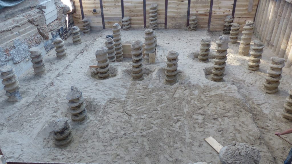
The Olivier pile is a cast-in-place, drilled full displacement concrete pile with a screw-shaped shaft along its full length. Depending on the design, the system is used as a reinforced foundation pile or as an inclusion for ground improvement.
Olivier supplies the technology and tooling, with practical support for rig configuration, design input and site start-up.
Key benefits
Up to 40% less concrete
Compared with a full cylindrical pile of the same outside diameter and length.
No excavated spoil
Soil is displaced, so there is no excavated spoil to remove from the site.
Screw-shaped shaft
The continuous helical profile contributes to load transfer between the pile and the ground.
Reinforcement before concrete
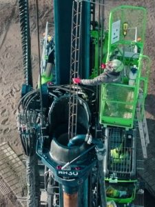
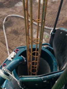
The reinforcement cage is lowered through the drill pipe to the required depth.
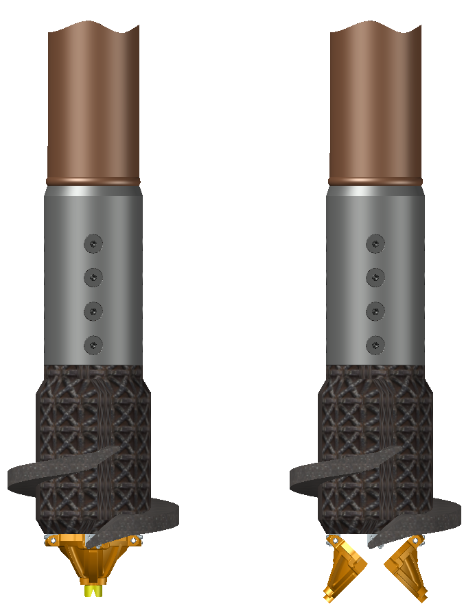
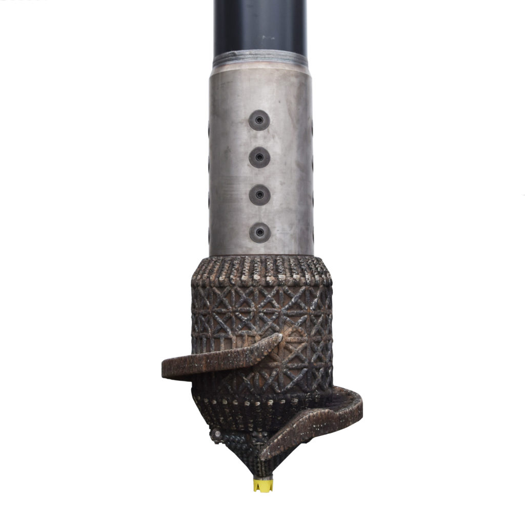
Olivier reusable drill tip
The drill tip returns to the surface with the auger head. No sacrificial tip is left behind.
Use existing rigs
The tooling can be configured for a suitable rig in your existing fleet.
How the screw-shaped shaft works
Just as a screw engages with wood differently from a smooth nail, a screw-shaped pile differs from a cylindrical pile. The Olivier pile has a continuous helical profile along its full length. The outside diameter of this profile is 200 mm larger than the core diameter.
Soil remains between the helical ribs. Concrete follows the screw-shaped pile body, so less concrete is needed than for a full cylinder of the same outside diameter and length. The final pile diameter, length and capacity are determined from the CPT data, loads and applicable design method.
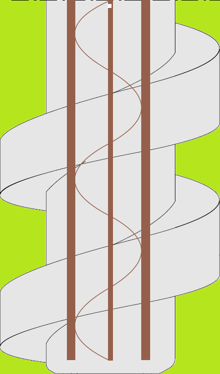
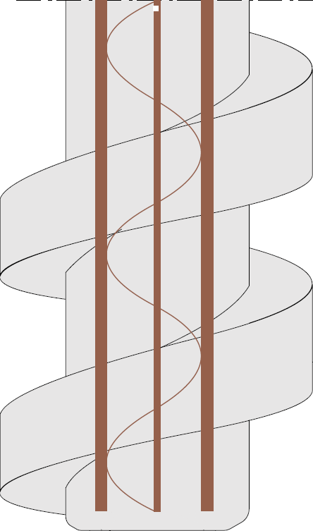
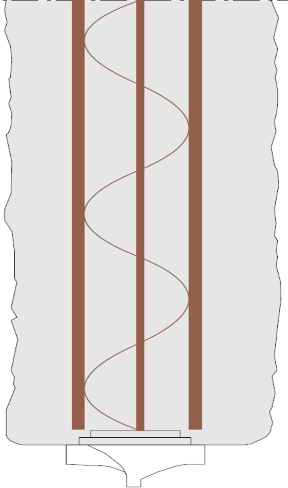
The green area shows the concrete volume saved. In an Olivier pile, soil remains in this space between the helical ribs. A full cylindrical pile of the same outside diameter and length would also contain concrete here. This compares concrete volume, not necessarily two designs with the same load-bearing capacity.
Installation sequence
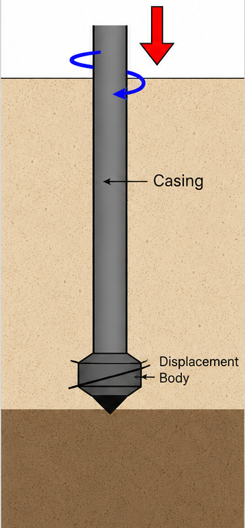
1. Drill down
The auger head is rotated clockwise to the design depth, displacing the soil laterally.
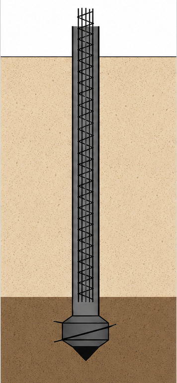
2. Reinforcement and concrete supply
Where reinforcement is required, the cage is lowered through the drill pipe. Concrete supply then starts.
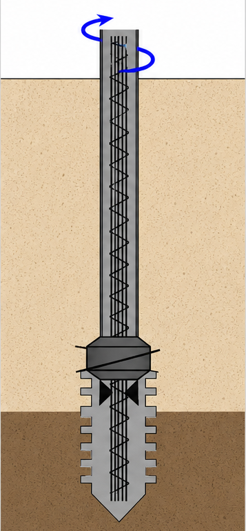
3. Controlled reverse extraction
The flaps open automatically as reverse extraction begins. Concrete supply and the extraction movement are coordinated to form the screw-shaped shaft.
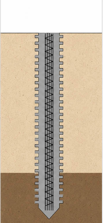
4. Completed Olivier pile
The drill pipe and auger head are recovered, leaving the cast-in-place concrete pile in the ground.
Open concrete system: reinforcement first
Reinforcement is positioned through the open passage in the drill pipe before concrete is supplied. During reverse extraction, concrete is fed into the pipe and its level is kept above ground level. The resulting gravity pressure is used to form the pile. A concrete pump supplies the concrete; pile formation does not rely on a closed pressure-filling system.
Olivier reusable drill tip
During drilling, the closed flaps form the drill tip. They open automatically during reverse extraction and return to the surface with the auger head. There is no need to fit a new sacrificial tip for each pile. This saves material and transport and avoids the associated handling operation beneath the auger head.
Ground conditions and rig configuration
Olivier piles can be installed in a range of displaceable soils, including clay, silt and sand. Suitability for denser or harder layers depends on factors including CPT data, pile diameter and available drilling torque. Olivier helps match the tooling and rig configuration to the project.
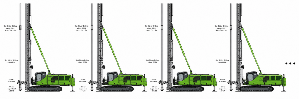
One drill-pipe set, several pile diameters
Changing the auger head allows several pile diameters to be installed with the same drill-pipe set. In the illustrated example, Ø324 mm pipes are used for Olivier piles from d36/56 to d51/71. The appropriate combination is selected for each configuration.
Foundation piles, ground improvement and inclined piles
Foundation piles
As a reinforced foundation pile, the Olivier pile transfers loads to the ground. Pile geometry and reinforcement follow the project design.
Ground improvement
The system can also be used as an inclusion for ground improvement. Inclusions are generally unreinforced; reinforcement can be added where required by the design.
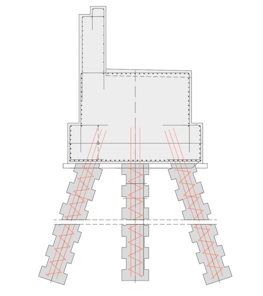
Inclined piles
Olivier piles can be installed at an inclination for applications with vertical and horizontal loads. Reinforcement is positioned through the drill pipe along the designed pile axis.
Pile diameters
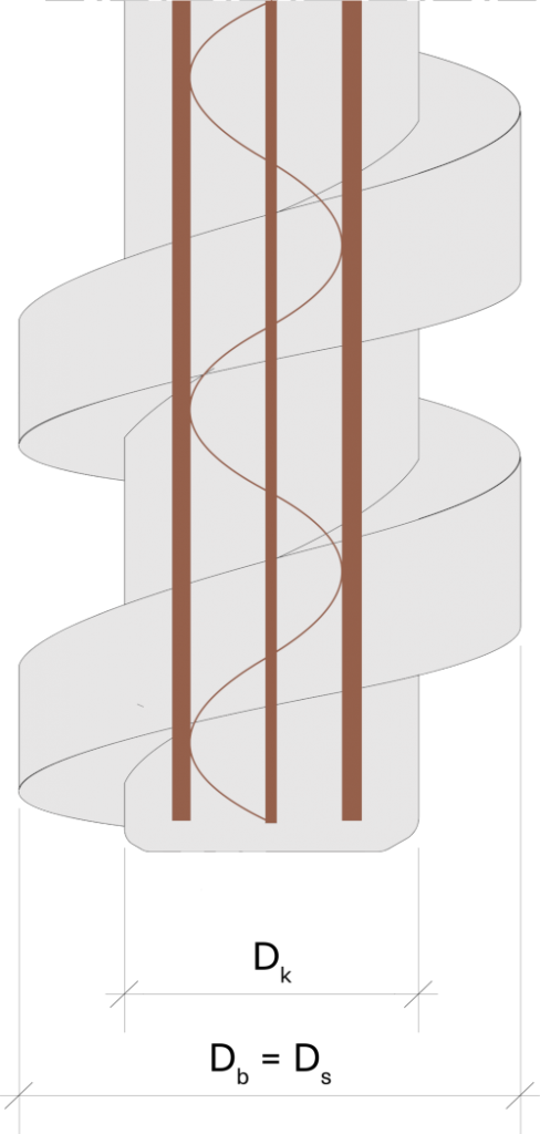
An Olivier pile is specified by two diameters: Dk/Ds. Dk is the core diameter. Ds is the outside diameter of the helical profile and also the pile base diameter Db. Therefore: Db = Ds.
An Olivier pile d36/56 has a 360 mm core diameter and a 560 mm outside diameter. These are two dimensions of the same pile, not a diameter range.
The outside diameter is used for geotechnical calculations of shaft and base resistance within the applicable design method. The core diameter governs the structural calculation of the concrete section. Final design takes account of ground data, loads and applicable requirements.
Standard Olivier auger-head sizes:
| Pile type | Core Dk | Outside Ds = Db |
|---|---|---|
| d31/51 | 310 mm | 510 mm |
| d36/56 | 360 mm | 560 mm |
| d41/61 | 410 mm | 610 mm |
| d46/66 | 460 mm | 660 mm |
| d51/71 | 510 mm | 710 mm |
| d56/76 | 560 mm | 760 mm |
| d61/81 | 610 mm | 810 mm |
| d66/86 | 660 mm | 860 mm |
Olivier in practice
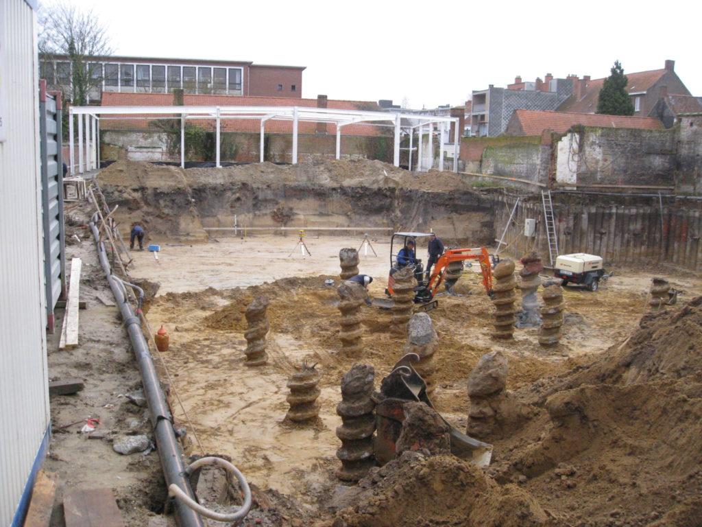
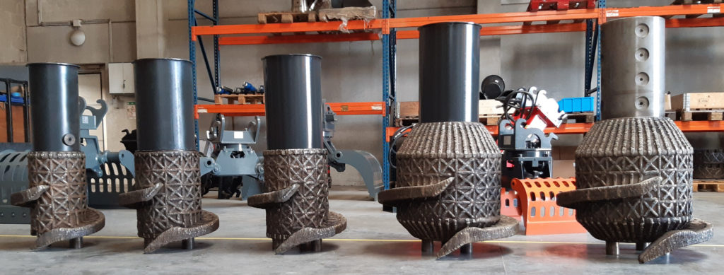
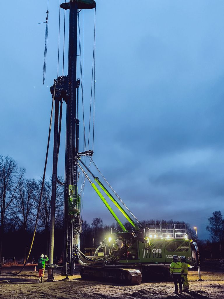
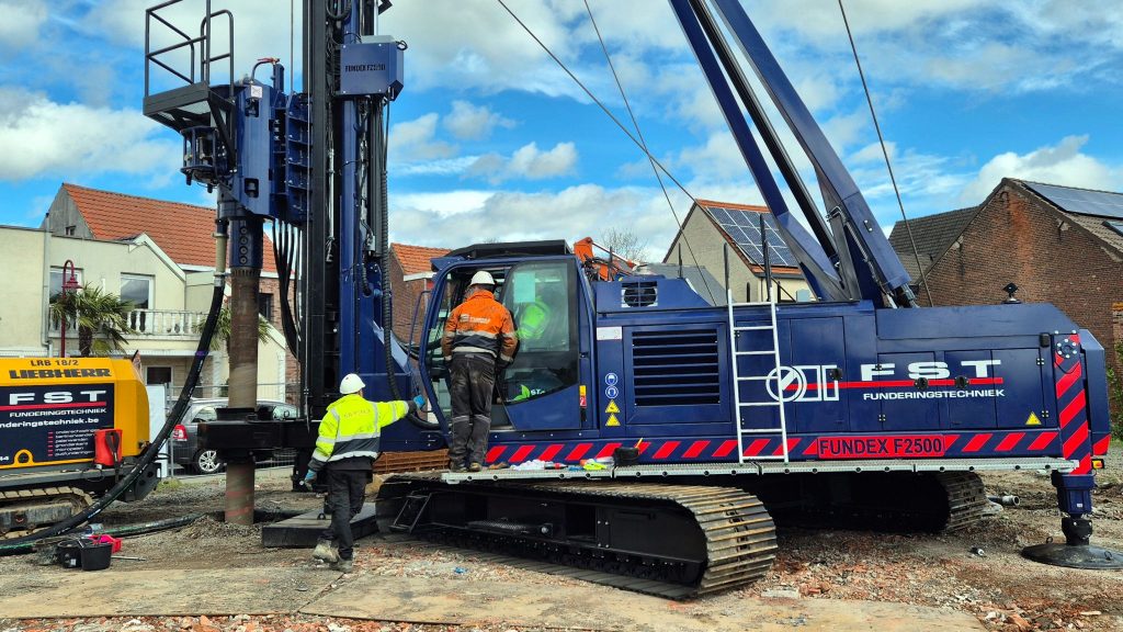
A selection of piles, tooling and rigs in use. Visit our references page for more site photographs.

From rig configuration to site execution
Tooling and rig configuration
Advice on auger heads, drill pipes, couplings and a suitable piling rig.
Design input
Support with pile geometry selection and CPT interpretation, within the applicable design framework.
Training and start-up
Practical crew training and support during commissioning and initial installation.
Site support
Practical assistance with installation questions and changing ground or site conditions.
More about training and support
Would you like to know whether the Olivier pile system suits your project and rig? Discuss your CPT data, required pile dimensions and available equipment with us.
Protected technology
Olivier technology includes solutions protected by patents and registered designs. Protection varies by solution and jurisdiction. Contact us for information about use and licensing.